From YAML to pixels - building the Vectra C dashboard
The last post ended with a YAML file and me saying the dashboard was next. It was next. It also took longer than I thought, which is probably the theme of this whole project.
In the car LS_CAN_IDS.yaml is useless until something reads those signals and puts numbers on a screen - so I had to actually wire the thing up, write firmware that isn't a hex grid, and somehow ended up bolting on Bluetooth and a gate opener because once there's a display in the dash you start thinking "well while I'm here…"
Only LS-CAN made the cut
Originally I wanted the full GMLAN tour - HS, MS, LS, three TWAI peripherals on the P4, three transceivers, the works.
MS-CAN isn't even on my OBD socket. I'd have to cut into the harness behind the radio, and my car has the cheap head unit anyway, so that idea died quietly. HS is there if you want engine ECU stuff, but almost everything I cared about for a custom cluster - doors, lights, stalks, wheel buttons, speed, RPM - lives on LS-CAN.
Firmware only starts that one bus now. Listen-only, TWAI2, 33.333 kbit/s. The sniffer-era multi-bus code is still in the repo gathering dust and can_dashboard.c never touches it. Debugging one bus at a time is headache enough.
Wiring it for real
Here's the whole mess at a glance:
  flowchart TB
    subgraph vehicle["Vehicle (Opel Vectra C)"]
        OBD16["OBD-II pin 16
12 V DC"]
        OBD1["OBD-II pin 1
LS-CAN SW 33.3 kbps"]
        OBD5["OBD-II pin 5
GND"]
    end

    subgraph power["Power chain"]
        INA["INA219
shunt + monitor"]
        XL["XL4015 buck
12 V → 5 V"]
        RAIL5["Common 5 V rail"]
        RAIL33["3.3 V from P4 board
header pins 1, 3, 18"]
    end

    subgraph dash["Guition JC4880P443C dashboard"]
        P4["ESP32-P4
main firmware"]
        DSI["ST7701 LCD
MIPI DSI"]
        TP["GT911 touch
I2C GPIO7/8"]
        SD["microSD
SDIO"]
        EXP["2×13 expansion header"]
    end

    subgraph exp_modules["Modules on expansion header / harness"]
        CAN["VP250
CAN transceiver"]
        BT["QCC5125 / FSC-AT
Bluetooth audio"]
        PCM["PCM5102 DAC"]
        GATE["ESP-01
gate UART bridge"]
        GPS["NEO-6M GPS
optional"]
    end

    OBD16 --> INA --> XL --> RAIL5
    OBD5 --- RAIL5
    RAIL5 --> P4
    RAIL5 --> BT
    RAIL5 --> PCM
    RAIL5 --> GPS
    RAIL5 --> INA
    RAIL5 --> XL
    P4 --> RAIL33
    RAIL33 --> CAN
    RAIL33 --> GATE

    OBD1 <-->|"LS-CAN GMLAN
single-wire"| CAN
    CAN <-->|"TWAI2 GPIO29/30
33.3 kbps listen-only"| P4
    BT <-->|"UART2 115200 AT/AVRCP
GPIO51 TX / GPIO52 RX"| P4
    BT -->|"I2S"| PCM
    GATE <-->|"UART3 115200
GPIO28 TX / GPIO32 RX"| P4
    GPS <-->|"UART1 9600 NMEA
GPIO50 TX / GPIO49 RX"| P4
    INA <-->|"I2C 0x40
ES_I2C pins 23/25"| P4
    P4 --> DSI
    P4 --> TP
    P4 --> SD
    EXP --> CAN
    EXP --> BT
    EXP --> GATE
    EXP --> GPS
    EXP --> INA
Power is OBD pin 16 into the INA219 shunt (so I can see rail voltage and how many milliamps this thing draws), then an XL4015 buck down to 5 V for the board, Bluetooth module, DAC, and the GPS module whenever I get around to soldering it. The P4's regulator feeds 3.3 V to the VP250 and an ESP-01.
  flowchart TB
    subgraph vehicle["Vehicle (Opel Vectra C)"]
        OBD16["OBD-II pin 16
12 V DC"]
        OBD1["OBD-II pin 1
LS-CAN SW 33.3 kbps"]
        OBD5["OBD-II pin 5
GND"]
    end
    subgraph power["Power chain"]
        INA["INA219
shunt + monitor"]
        XL["XL4015 buck
12 V → 5 V"]
        RAIL5["Common 5 V rail"]
        RAIL33["3.3 V from P4 board
header pins 1, 3, 18"]
    end
    subgraph dash["Guition JC4880P443C dashboard"]
        P4["ESP32-P4
main firmware"]
        DSI["ST7701 LCD
MIPI DSI"]
        TP["GT911 touch
I2C GPIO7/8"]
        SD["microSD
SDIO"]
        EXP["2×13 expansion header"]
    end
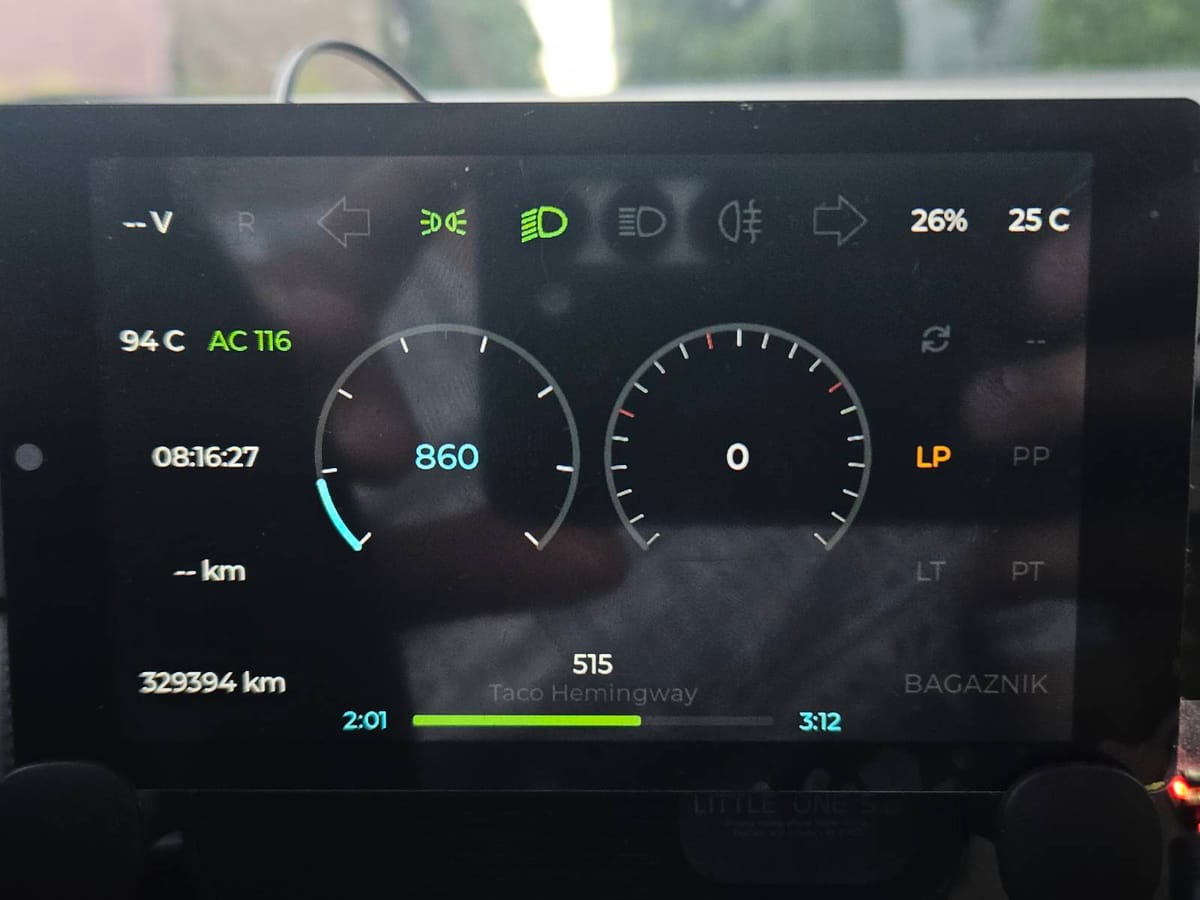
The screen
JC4880P443C, 4.3 inch panel, LVGL 9, all C. Physically portrait, rotated to 800×480 landscape in software.
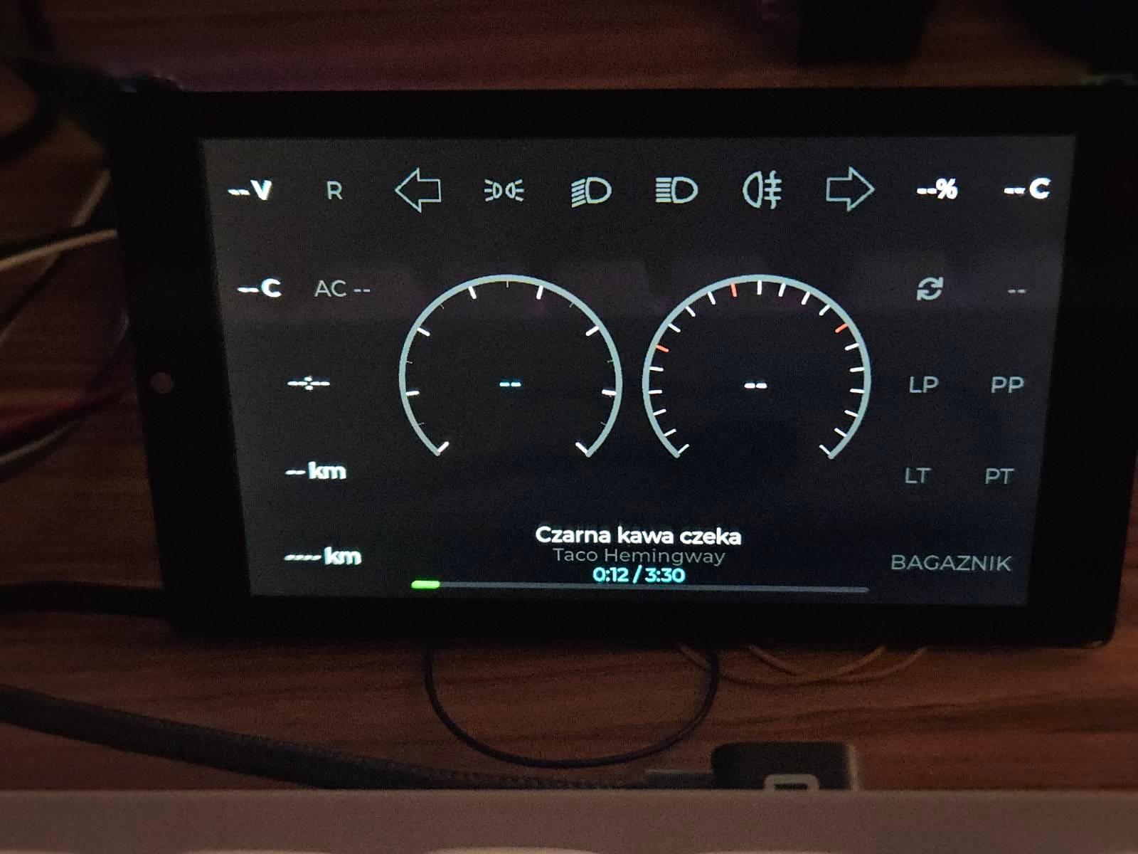
I mocked the layout in WPF because dragging boxes around is faster than guessing LVGL coordinates, then ported the grid into obd_dashboard_vis.c with RPM and speed rings in the middle, lamp icons along the top, doors and odometer around the edges. Values come straight from the YAML catalog - can_ls_read_phys() by signal name on frames like 0x108 for RPM/speed, 0x260 for blinkers, 0x230 for doors, and so on. Same decode maths as the last post, I just stopped squinting at hex.
You can swap gauge styles, pick a colour theme, hide whole sections if door labels annoy you.
Trip meter took longer than it should've because the car doesn't broadcast trip distance anywhere obvious. I'm integrating wheel pulses from the speed frame and scaling by tyre size from the menu; it resets when the engine stops and tells me roughly how far since I left the house. Close enough.
CAN frames land in a cache and the UI only redraws when something actually changed. When the bus gets chatty, frames get dropped on purpose; I'd rather a smooth speed needle than a log of every copy of 0x315. Bus-off recovery code is still there in case something goes wrong way.
Wheel buttons
This is what I wanted when I bought the car seven years ago - buttons on the wheel that control my thing.
They show up on frame 0x175, byte 3. When the settings menu isn't open, left and right skip tracks through a QCC5125 Bluetooth module on UART2 (unfortunately this also controls factory radio unit too - possibly disconnecting OBD from it would solve everything), the phone button play-pauses, and +/- nudge volume with a little bar on screen. I send it AT+PV / AT+PN / AT+PP for AVRCP and occasionally get title, artist, and progress back as +TITL / +ARTS / +PYPS when the module feels like cooperating.
Audio never goes near the ESP32 - QCC5125 out to a PCM5102 DAC and amp over I2S, and the P4 just acts as a remote with a display. I wasn't about to fight the P4 I2S driver for something a UART module already handles.
Hit OK on the wheel and a settings overlay opens on the same buttons: units, gauge style, tyre size, what to show. Labels are in Polish because it's my car. While I was at it I hung gate controls and a screen showing CPU load and INA219 readings off the same menu.
Gate, GPS, and other crimes
Unrelated to the Vectra but there was a free UART: an ESP-01 on UART3 running separate firmware, dumb newline text protocol (OPEN, CLOSE, GET_INFO at 115200). Dashboard sends commands, ESP-01 does whatever RF nonsense the gate motor needs.
GPS on UART1 parses NMEA into a little position bar. I wired it, tested it, turned it off in config. Might enable it again to log a drive, log driven routes or do something when close to some kind of location.
Where things stand
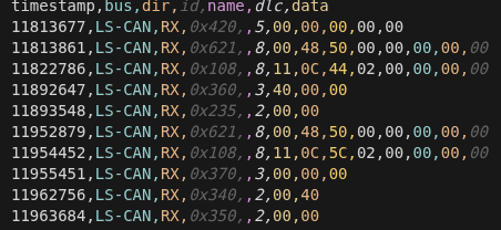
MS and HS still aren't connected. Half the YAML is guesswork - that 0x621 cluster from the decoding post is still a mystery and the screen ignores it. No install photos I'm happy with yet. But the thing sits in the car, wheel buttons skip my music, blinkers blink on screen when I hit the stalk, and that's weirdly satisfying for how many weekends it ate.
So... what's next?
HS-CAN and MS-CAN are definitely not abandoned - maybe I’ll use them in the future, but that would require much closer integration between the ESP32 and my car’s internals.
Another idea is to go with a bigger (7-inch) display and replace the instrument cluster altogether, because why not? (Also add more thingamajigs: more screen space means more things you can show at once.)
Swapping the factory radio unit (or disconnecting it from the CAN network) for a newer one is also something to consider - honestly, right now I mostly just need an audio amplifier, since the sound comes from Bluetooth.
In the center panel above the radio, there’s a factory display opening that accidentally fits a 4.3-inch screen perfectly - maybe I can cut out the original one to fit this build (and then go with a 7-inch screen as the instrument cluster and make them talk? Like: one ESP32-P4 decodes CAN messages and displays gauges, while another one acts as the media controller?)
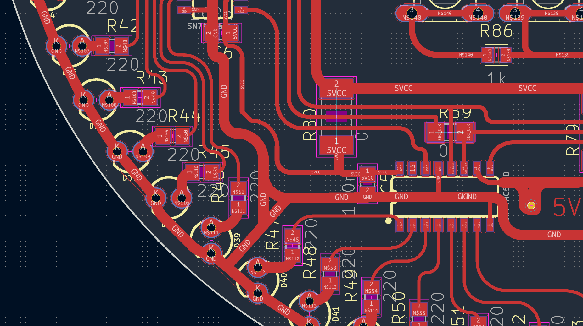
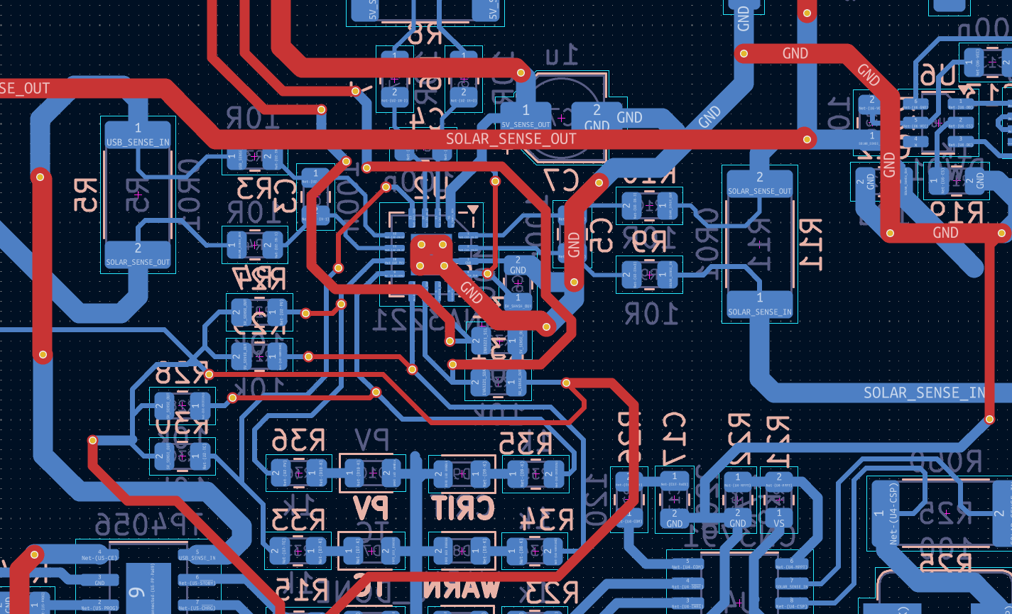
First thing to do next is to make proper PCB for all modules ESP32 is using.
As you CAN see, there are many ways to improve or extend this, but for now these are just random ideas.
Hopefully there will be enough free time to bring at least one of those ideas from fantasy to reality.