Building a round LED clock from scratch: The art of unnecessary complexity
Overcomplicating things at its finest...
I was always looking for a challenge during my Computer Science studies (almost 3 years ago at the time of writing...). When the professor offered a lecture exemption for any project that proved we already knew the material, I immediately knew what I had to do: build something new.
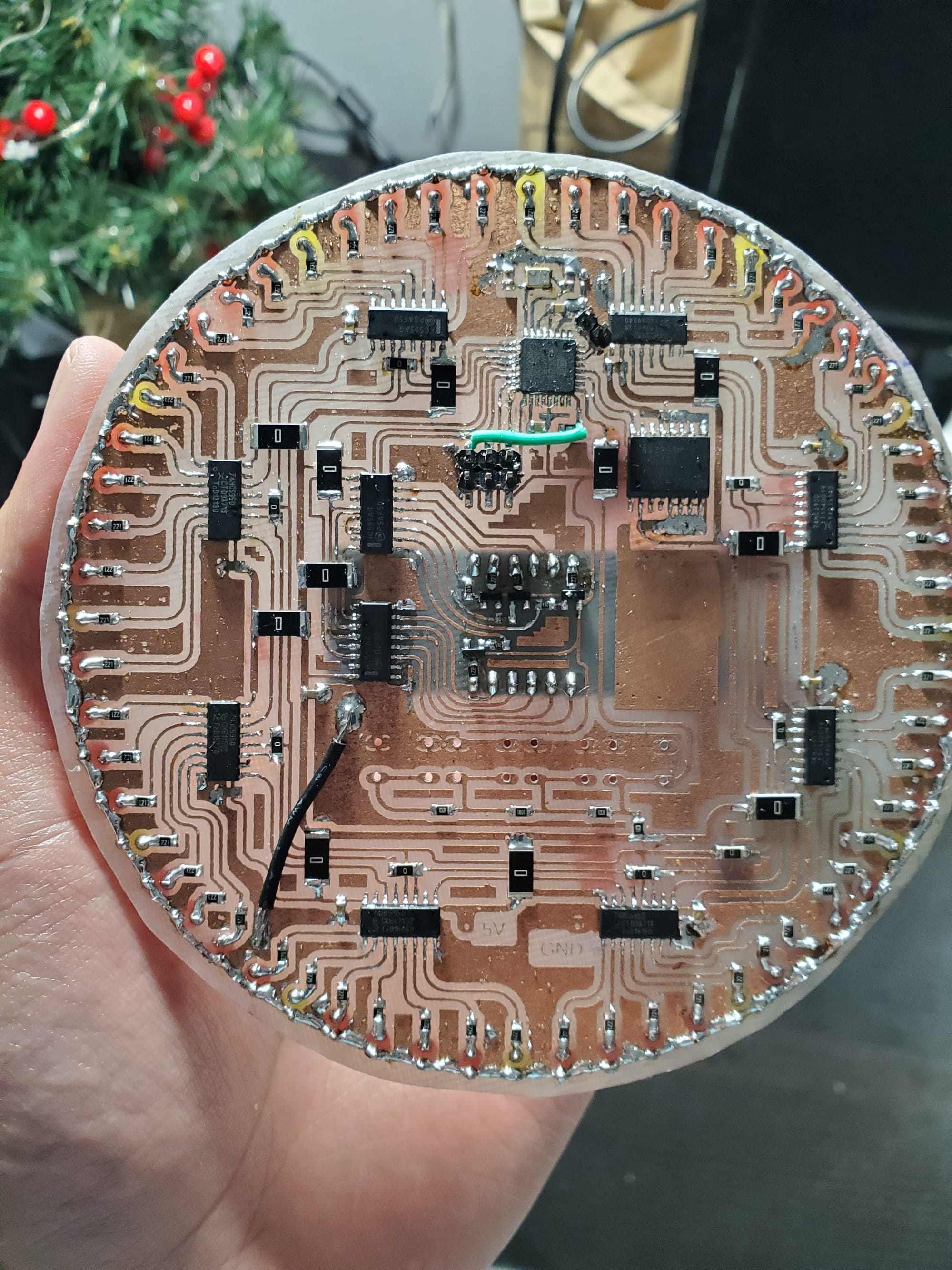
Naturally, instead of doing something sensible like using individually addressable WS2812B (NeoPixel) LEDs, I took the most scenic, complicated route possible. I designed, etched, drilled, and hand-soldered a round, single-sided PCB clock featuring an ATmega328p, a high-precision DS3231 Real-Time Clock, 10 shift registers, 60 individual LEDs mapping the seconds, and a 4-digit 7-segment display right in the center.
Fabricating the PCB: from raw FR4 to board
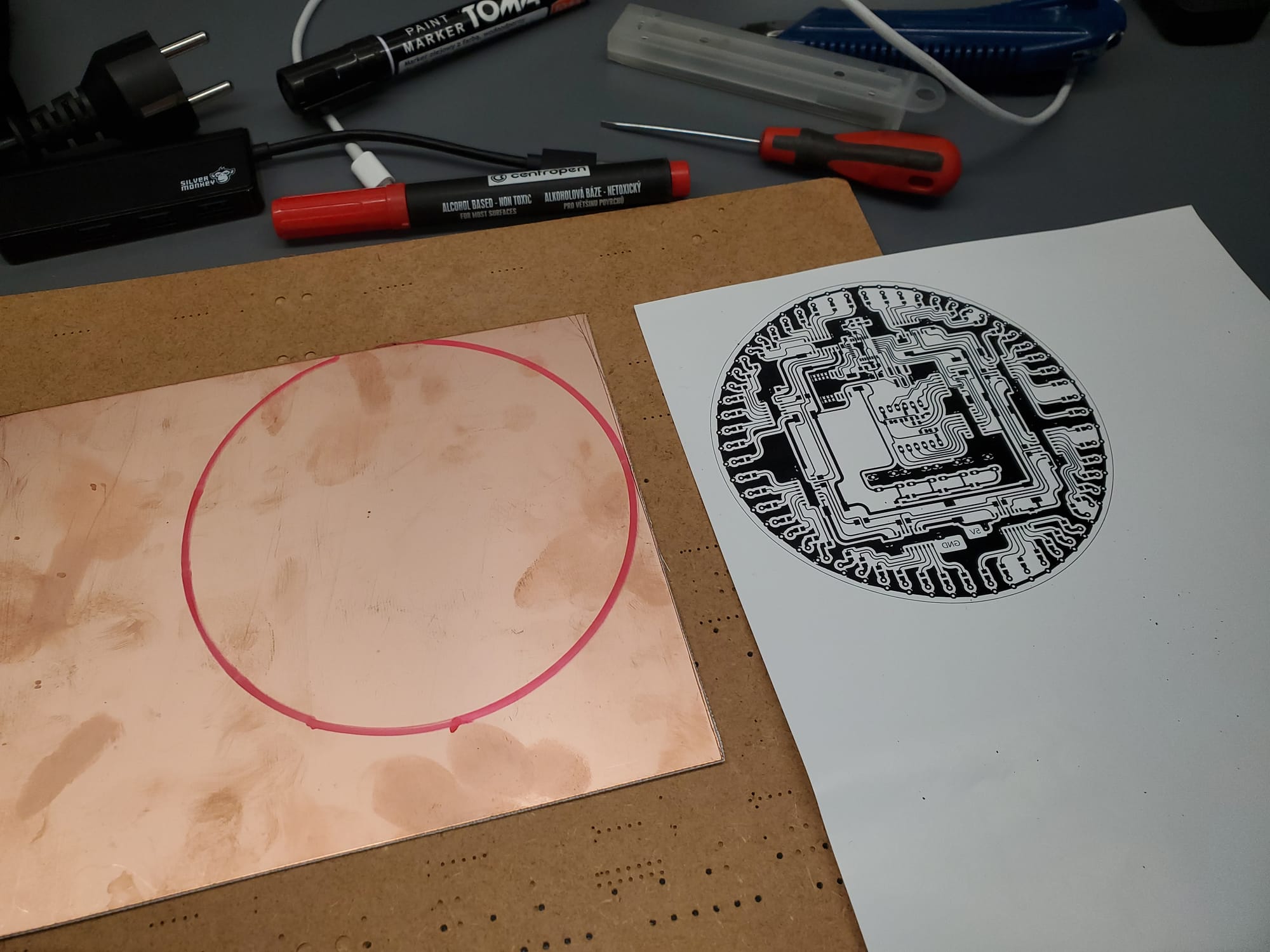
This wasn't a factory-ordered board from JLCPCB. This was pure, old-school garage manufacturing:
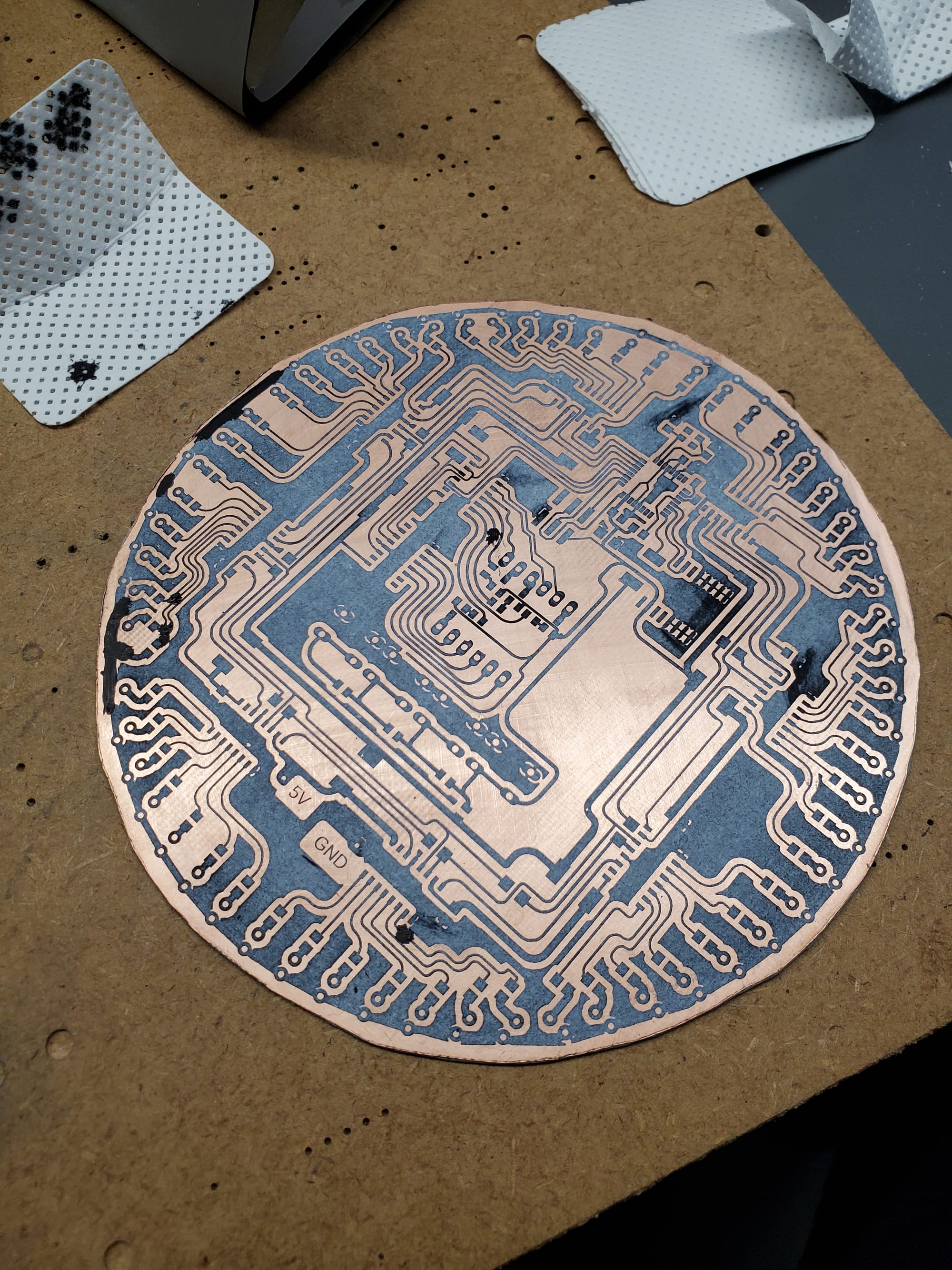
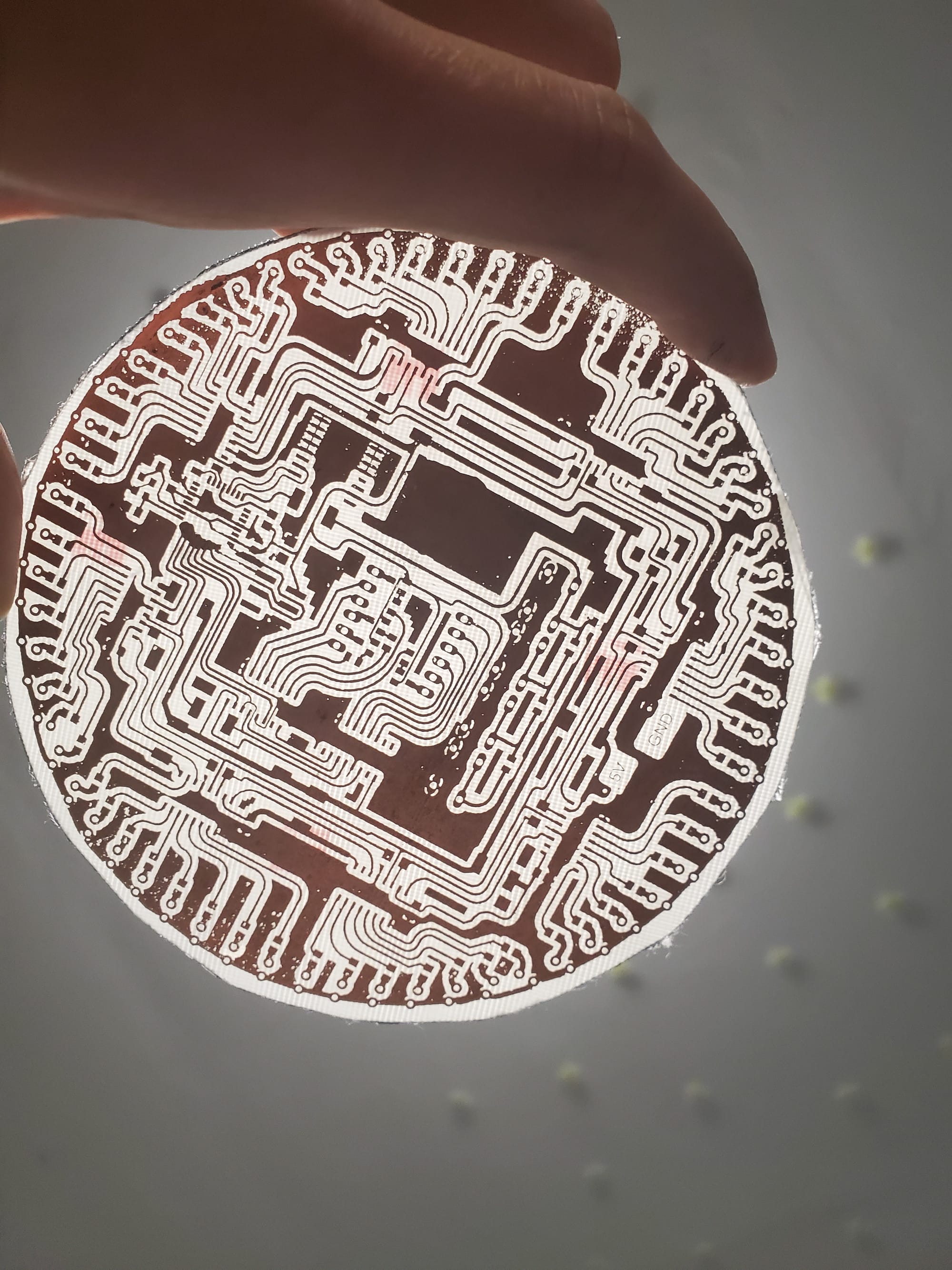
- Thermal Transfer: I printed the trace design onto glossy paper using a laser printer and ironed the toner directly onto a raw, naked FR4 copper wafer.
- Chemical Etching: The board went into a bath of Sodium Persulfate (B327) to dissolve away the unprotected copper.
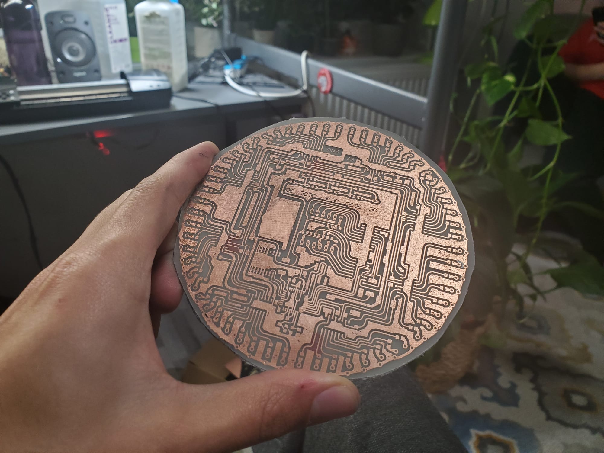
- Drilling & Populating: I hand-drilled tens of holes for the through-hole components, polished the copper, and spent hours hand-soldering every connection.
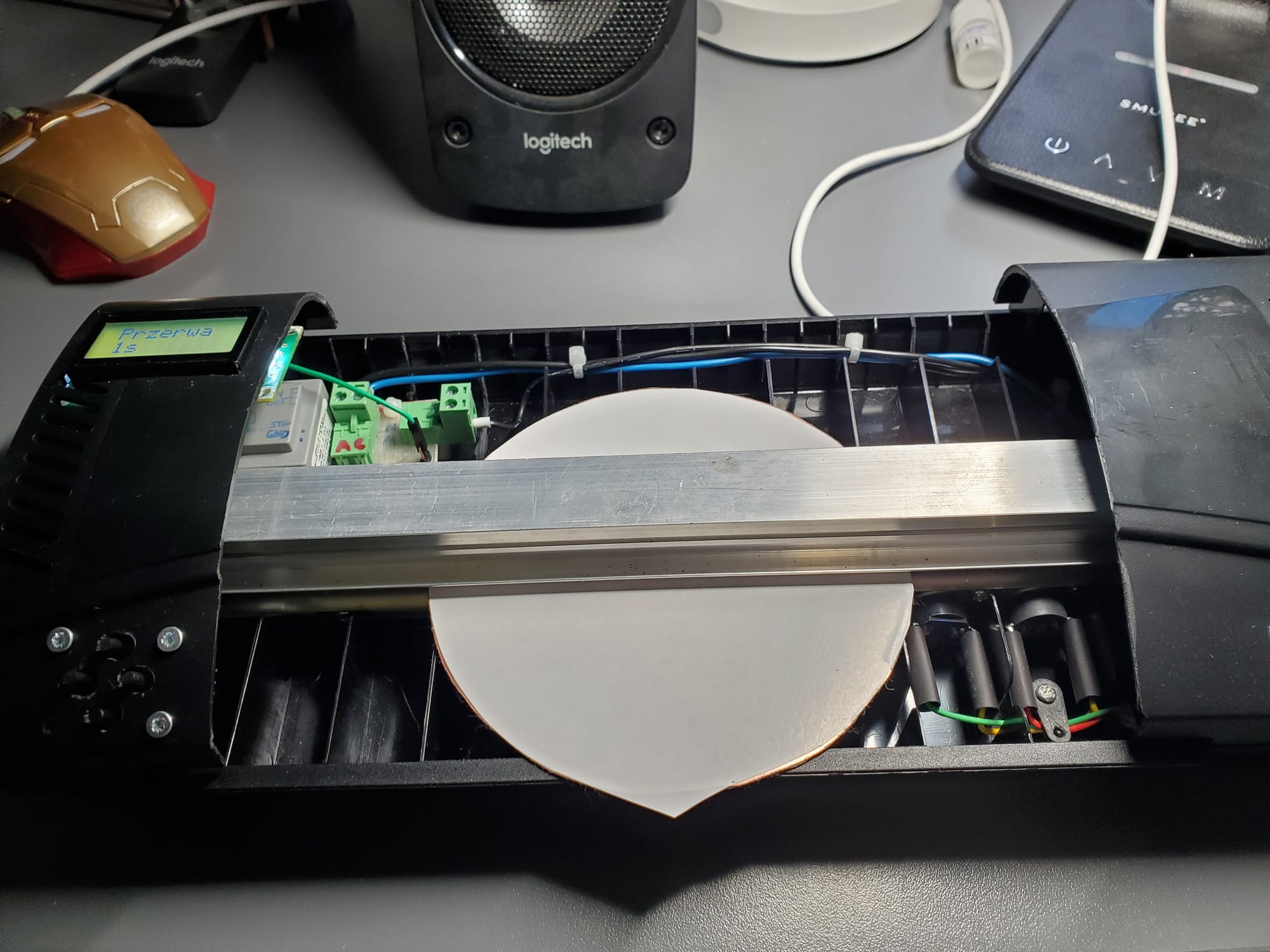
The device you see in the second image is my homemade thermal-transfer machine. Built to avoid using a standard clothes iron, it has proven to be incredibly effective due to its even heat distribution and uniform pressure across the entire PCB - something that required much more effort and attention when doing it manually with an iron.
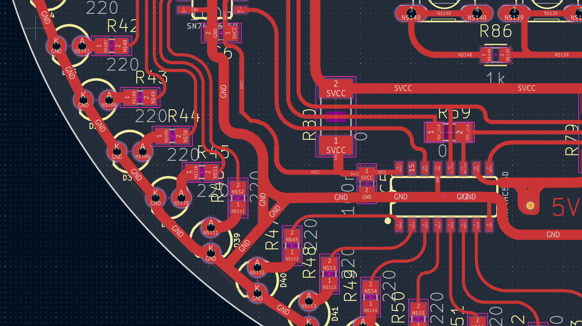
Thin traces (12 mil - that's only 0.3mm!) turned out wonderfully for homemade PCB - no tearing, sharp edges.

The hardware architecture
The core requirement of this build was aesthetics. Because the front of the round PCB is the clock face, I absolutely refused to use dual-layer routing, vias, or jumper wires on the top side. Everything had to live on a single copper layer on the back (yeah, I know that professionally made PCB would look lot better even double-sided but that's not the point here - PCB had to be homemade).
This aesthetic constraint dictated the entire component architecture:
- Microcontroller: ATmega328p running MiniCore bootloader with a external 12MHz crystal.
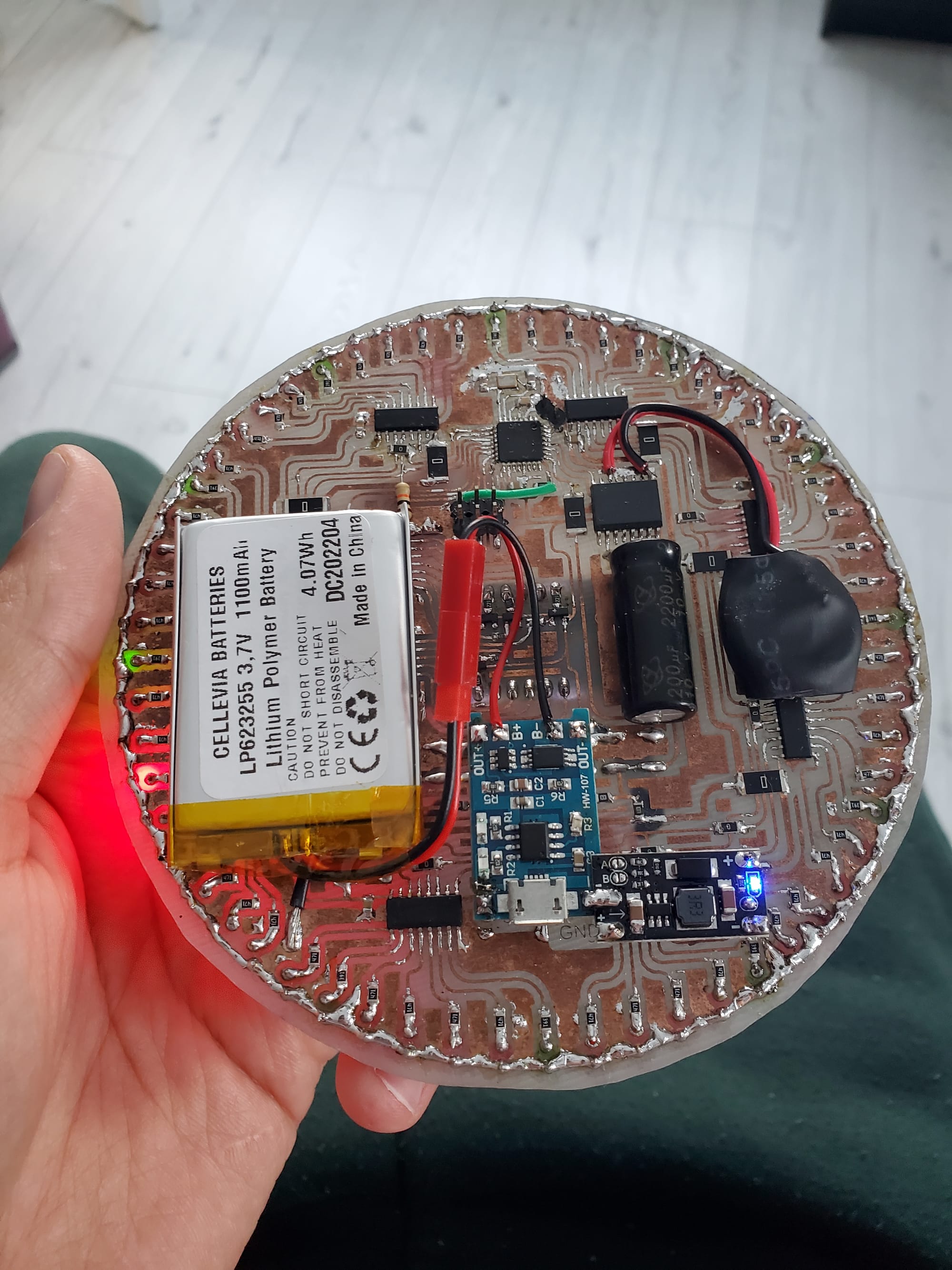
- Timekeeping: DS3231 RTC IC backed up by a CR2032 lithium coin cell (keeps time even when main power is disconnected).
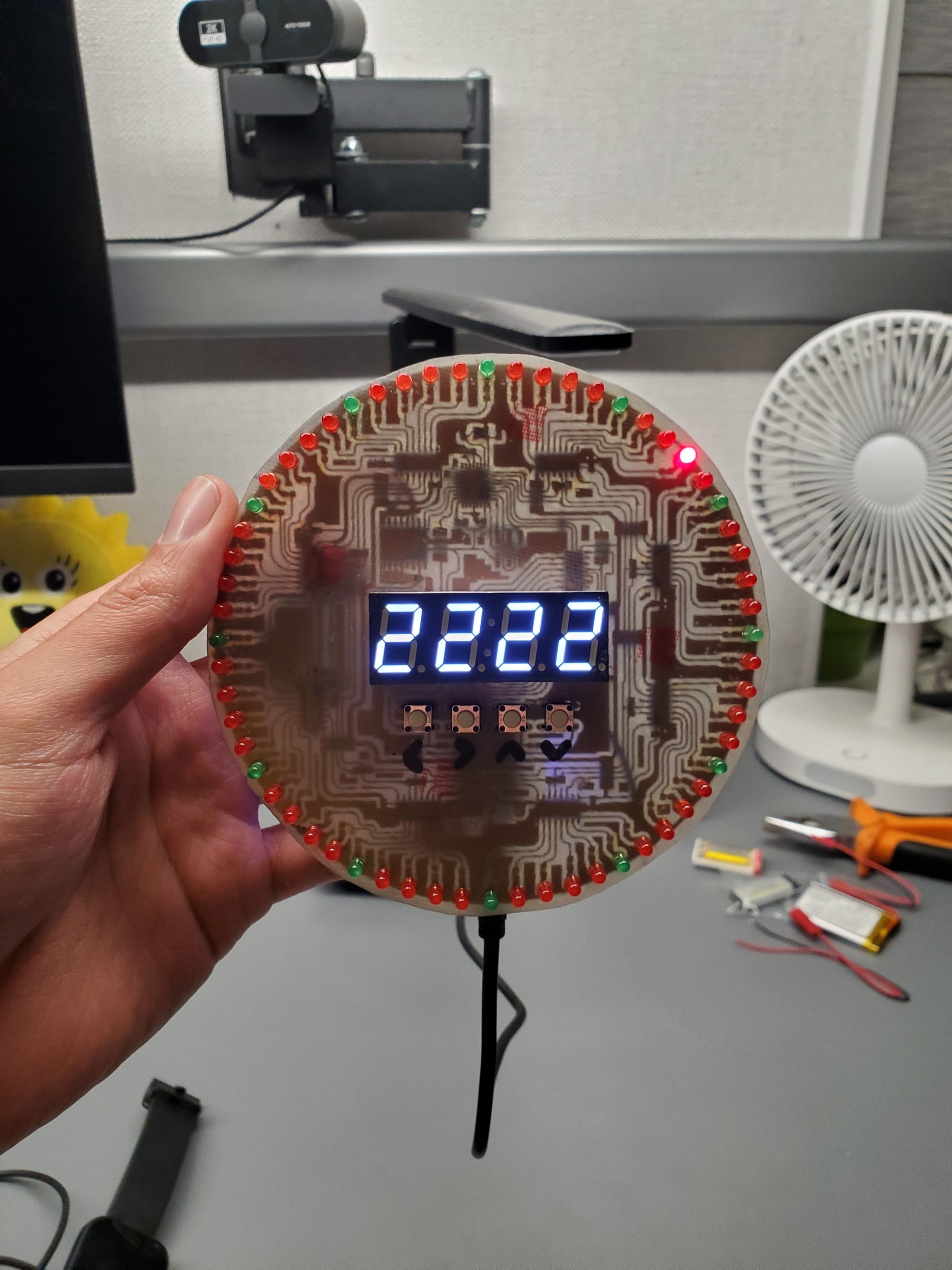
- The Outer Ring: 60 discrete LEDs showing the progress of seconds, driven by 8 cascaded 74HC595 shift registers.
- The Center Display: A 4-digit, 7-segment display showing hours, minutes, dates, and settings, driven by an additional 2 74HC595 shift registers.
- Power System: A single 3.7V Li-ion battery boosted to 5V via a small step-up converter, managed by a TP4056 charging module.
- User Interface: 4 analog-multiplexed pushbuttons underneath the display for navigation and programming.
Software
The single-sided routing constraint meant I couldn't easily route the hardware SPI pins (MOSI, SCK) from the ATmega328p out to the LED shift registers without crossing traces. To solve this, I used custom digital pins and implemented Bit-Banged SPI.
While this saved the PCB layout, it introduced a fascinating engineering trade-off: loop latency. Because the microcontroller has to manually toggle IO pins in software to push data to the 8 LED shift registers (bbSPI), it eats up valuable CPU cycles. This is why you can catch a tiny hint of visible refreshing/flickering on the central 7-segment display if you look closely - the loop() takes just a bit too long to execute when updating the second ring.
Handling the analog buttons on a single pin
To save GPIO pins for the shift registers, all 4 pushbuttons are tied to a single analog input (A2) using a resistor divider network.
enum Btn { btnNONE, btnUP, btnDOWN, btnLEFT, btnRIGHT };

int readAnalogButton() {
  const int v = analogRead(BTN_PIN);
  if (v < 100) return btnLEFT;
  if (v < 550) return btnRIGHT;
  if (v < 725) return btnUP;
  if (v < 850) return btnDOWN;
  return btnNONE;
}
Updating the 60-LED ring
Because tracing a perfect circular matrix on a one-sided board is a nightmare, the LEDs aren't perfectly sequential in hardware. I solved this in software using an array mapping (adjustedSeconds) to align the physical layout with actual time.
void updateSecondRing() {
  if (second == 0) clearLED(0);
  clearLED(adjustedSeconds[prevSecond]);

  // Keep the 5-second ticks illuminated
  for (int i = 0; i < second; i++)
    if (i % 5 == 0) setLED(adjustedSeconds[i]);

  refreshLEDs();
  setLED(adjustedSeconds[second]); // Light up current second
  refreshLEDs();
  prevSecond = second;
}
The UI state machine
The clock features 10 different "screens" controlled by screenId. Screens 0-4 handle normal display modes (Time, Date, Year, Blank, and the "SET" prompt). Screens 5-9 drop the user into an active editing menu where the internal variables for minutes, hours, days, months, and years can be manipulated before writing them back to the DS3231 RTC.
void adjustField(int page, int d) {
  switch (page) {
    case 5: // Minutes
      minuteToSet += d;
      if (minuteToSet > 59) minuteToSet = 0;
      else if (minuteToSet < 0) minuteToSet = 59;
      break;
    case 6: // Hours
      hourToSet += d;
      if (hourToSet > 23) hourToSet = 0;
      else if (hourToSet < 0) hourToSet = 23;
      break;
    // Continuing through days, months, and years...
  }
}
Lessons Learned & Conclusion
Did I need to use 10 shift registers, map a 60-LED custom array, bit-bang my SPI, and etch a giant circular board by hand in an acid bath just to avoid attending a few lectures? No. But as a future engineer, doing things the "unnecessarily complicated way" felt most natural (and is often where you learn the most).
Project Status: Passed. Classes skipped successfully. 😎